
Views: 0 Author: Site Editor Publish Time: 2026-08-23 Origin: Site


Installing a pet baffle ceiling requires balancing acoustic performance targets, visual spatial dynamics, and strict MEP (Mechanical, Electrical, Plumbing) integration constraints. Modern commercial environments often struggle to achieve quiet, focused zones. Hard surfaces dominate these open designs. They look beautiful but create harsh, echoing acoustic environments. Poorly specified baffles lead to acoustic dead zones, budget overruns, or interference with HVAC and fire suppression systems. Many designers mistakenly assume all baffle arrays perform equally in any room. This oversight causes severe sound reflection issues later. This guide outlines the exact decision frameworks architects and facility managers use to specify baffle spacing, suspension height, and panel orientation for optimal commercial performance. You will learn to optimize layout geometries for acoustic clarity. We will show you how to navigate compliance easily while elevating interior aesthetics.
Spacing determines how well a suspended ceiling absorbs unwanted noise. The distance between PET acoustic ceiling baffles directly affects the room's reverberation time (RT60). Installers typically space these panels at 6-inch, 12-inch, or 18-inch intervals on center. Closer gaps create denser acoustic coverage areas. They catch sound waves before they bounce off the hard deck above. Wider gaps allow more sound to escape into the ceiling plenum. This increases the total acoustic decay time. You must balance this density carefully against the specific use case of the room.
Acoustic absorption relies on total Sabins per square foot. Tighter spacing yields higher total Sabins overall. You might assume maximum density always provides maximum acoustic relief. However, acoustic returns diminish quickly if you space panels too closely. Sound waves cannot properly penetrate narrow gaps. They treat a densely packed baffle ceiling like a flat, reflective plane. This phenomenon severely limits the absorption of mid-to-high frequencies. Architects aim for an optimal middle ground. They calculate the exact Sabin requirement based on room volume and hard surface ratios.
Material volume directly drives up initial project budgets. Doubling the panel density doubles the material costs. It also doubles the hardware and labor required for installation. We recommend establishing a baseline spacing metric based on space utility. Dense spacing works best for bustling open-plan offices or call centers. Wider spacing suits transit corridors, large cafeterias, or transitional lobbies. You should plot these variations before finalizing the design.
Baffle Spacing and Performance Chart
| Spacing (On Center) | Acoustic Absorption Impact | Ideal Application Space |
|---|---|---|
| 6 Inches | Maximum high-frequency absorption | Open offices, busy restaurants |
| 12 Inches | Balanced mid-range frequency control | Conference rooms, retail stores |
| 18+ Inches | Minimal acoustic control, high visual impact | Hallways, transit corridors |
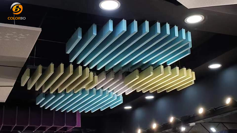
The suspension height from the structural deck creates a powerful acoustic trap. A larger air gap dramatically improves the absorption of lower frequencies. Sound waves travel up past the baffles and bounce off the structural ceiling. They then travel back down through the baffle array. This double-pass effect increases the total acoustic efficiency. Lower frequencies possess longer wavelengths. They require deeper air cavities for effective attenuation. Dropping the system further from the deck captures the bass frequencies typical of HVAC machinery.
Exposed structural ceilings look modern but present visual clutter. Ductwork, plumbing, and cable trays disrupt clean architectural lines. You must determine the exact drop height needed to obscure these elements visually. Baffles provide an excellent line-of-sight barrier. They hide ugly utilities without blocking access. Maintenance teams can still reach valves and junction boxes easily. They simply reach between the rows or unclip a single panel. You should map the lowest hanging MEP fixture first. Use that measurement to establish your minimum ceiling suspension plane.
Lighting significantly complicates ceiling drop heights. You must align the suspension plane with pendant lighting or linear LED fixtures. Mismatched heights create severe hard shadowing across the floor. They also cast unpleasant shadows on the acoustic panels themselves. Recessed lighting often requires custom cutouts. Pendants drop between the rows seamlessly. Ensure uniform lumen distribution by coordinating the lighting grid with the acoustic grid. Ask your lighting designer to verify the photometric plan alongside the acoustic layout.
Panel orientation dramatically impacts how occupants perceive and navigate a commercial space. Linear alignments naturally guide visual traffic. They draw the eye down long corridors or toward primary building exits. We use continuous linear runs extensively for subconscious wayfinding. Cross-hatch or grid layouts serve a different purpose entirely. They provide multidirectional sound diffusion. A grid traps sound from multiple angles simultaneously. Lobbies and large gathering areas benefit from this geometric complexity. The intersecting lines break up visual monotony and deliver superior acoustic comfort.
Large commercial interiors require diverse acoustic treatments. Open areas need broad reverberation control. Private spaces demand highly focused speech privacy. You can signify zone changes using simple orientation shifts. Transitioning from standard linear baffles to localized, high-density meeting room acoustic panels creates a distinct acoustic boundary. The visual shift tells occupants they have entered a quiet zone. This strategy isolates noise effectively without building permanent drywall partitions.
Rigid architectural lines sometimes feel too clinical. Designers use undulating bottom edges to soften these environments. Curved baffle layouts mimic natural topographies. They create dynamic, flowing ceilings. CNC manufacturing allows for intricate wave patterns and custom geometries. However, these customizations carry specific project implications. Complex cuts increase CNC manufacturing lead times significantly. They also generate more material waste during production. You should reserve highly sculpted contours for high-impact areas like reception desks or executive boardrooms.
Environmental compliance acts as the foundation of modern commercial design. You cannot overlook material safety standards. E0 acoustic ceiling baffle panels represent the highest tier of indoor air quality safety. The E0 emission standard guarantees negligible formaldehyde off-gassing. Zero-formaldehyde PET is a mandatory baseline for commercial and educational environments today. Poor air quality leads to sick building syndrome. It causes headaches, fatigue, and respiratory issues for occupants. Specifying E0 materials directly supports major building certifications like LEED and WELL.
Ceiling-suspended materials pose unique fire safety risks. Flames travel quickly across continuous overhead surfaces. You must verify Class A (ASTM E84 / EN 13501-1) fire propagation compliance. This standard measures both the flame spread index and the smoke developed index. Class A materials resist ignition and limit fire expansion. They also produce minimal toxic smoke when exposed to high heat. Never specify untreated acoustic foams or low-grade plastics in commercial plenums. Building inspectors will halt construction if ceiling materials fail fire compliance checks.
PET material feels exceptionally light in the hand. It typically weighs between 1.5 and 3 kg/m². Installers love working with it because it reduces lifting fatigue. However, cumulative weight becomes a critical engineering factor. High-density baffle designs pack hundreds of panels into a single room. This aggregate load places stress on the suspension grid and deck anchors. You must require verified load calculations from your structural engineer. They will assess the pull-out strength of the concrete anchors. They also determine if the existing grid requires supplemental wire ties.
Execution separates a good design from a successful installation. Choosing the right suspension hardware heavily influences the final aesthetic. Aircraft cable provides a remarkably clean, floating appearance. The thin metal wires virtually disappear against a dark deck. However, cable systems require meticulous, time-consuming leveling. Installers must adjust each wire individually to maintain a flat plane. Unistrut or channel tracks offer a rigid alternative. Tracks allow for much faster alignment. You simply slide the panels into place. The trade-off involves higher visibility. Tracks look distinctly industrial.
Lightweight acoustic baffle ceiling tiles interact unpredictably with active HVAC systems. Aggressive diffusers push high-velocity air across the ceiling plane. This airflow catches the flat sides of the panels. It causes them to sway or flutter continuously. Constant motion stresses the suspension hardware and creates visual distraction. You must define strict offset distances from supply vents. Maintain at least 24 to 36 inches of clearance between a directional diffuser and the nearest panel face. Consult your mechanical engineer to review throw patterns before finalizing the acoustic layout.
Poor construction sequencing ruins expensive acoustic materials. PET panels attract dust readily. They also suffer from impact damage if mishandled by other trades. You must dictate a strict order of operations in the project manual. The MEP rough-in must finish entirely before acoustic work begins. Follow this proven sequencing logic:
This sequence prevents staging conflicts. It ensures electricians do not move panels out of the way to reach junction boxes later.
The optimal acoustic ceiling design relies on a proven, mathematical formula. You must balance targeted NRC goals, precise MEP clearances, and the allocated budget per square foot. Tighter spacing yields better absorption but requires careful cost management. Proper drop heights leverage the hidden plenum to trap low frequencies seamlessly. Thoughtful panel orientation turns simple ceilings into powerful wayfinding tools. Always prioritize E0 and Class A safety standards to protect building occupants. Finally, encourage your specifiers to request a formal acoustic calculation report. Review a physical sample of the exact baffle profile, hardware, and colorway prior to finalizing your construction documents.
A: Generally 8 to 12 inches on center. However, this must be adjusted based on the structural ceiling height and specific acoustic targets of the room. High-volume spaces with excessive hard surfaces may require tighter arrays to achieve the desired sound decay.
A: Yes. Installers can modify standard PET panels with sharp utility blades. However, factory CNC-cut penetrations are strongly recommended. Factory cuts maintain clean visual edges, preserve structural integrity, and prevent ugly fraying around critical safety fixtures.
A: Baffles expose two sides of the panel to ambient sound waves. This orientation significantly increases the total absorptive surface area per linear foot compared to flush-mounted flat panels. They trap sound much more efficiently in large, open-volume ceilings.
A: Rarely. PET is exceptionally lightweight compared to wood or metal. Standard ceiling grids or direct-to-deck anchors typically handle the load easily. Nonetheless, local building codes must be consulted to verify specific seismic sway bracing requirements for suspended systems.